Obd1 engine harness diagram honda elegant wilbo666 1jz gte jzz30.
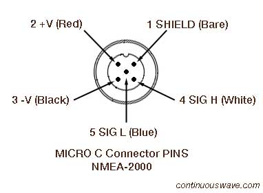
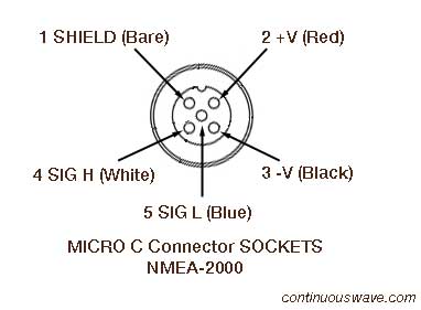
Nmea 2000 cable pinout.
As you can see the pin out is.
The gfs 10 fuel sensor as shown by the shaded components on the box diagram is intended to be connected to an existing nmea 2000 network on your boat.
A nmea 2000 power cable an additional drop backbone cable and additional t connectors are not included with a gfs 10 fuel sensor.
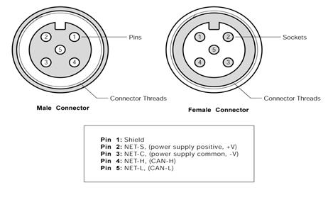
The drain wire shields the signal power and ground wires from external radio frequency interference rfi and helps reduce rfi emission from the cable.
National marine electronics.
Nmea 2000 wiring diagram collections of grmnais600 marine transceiver user manual garmin international inc.
Nmea 2000 connector pinout smart.
Two signal wires power and ground wires and a drain wire.
The micro c micro change connector is used on thin backbones light cable.
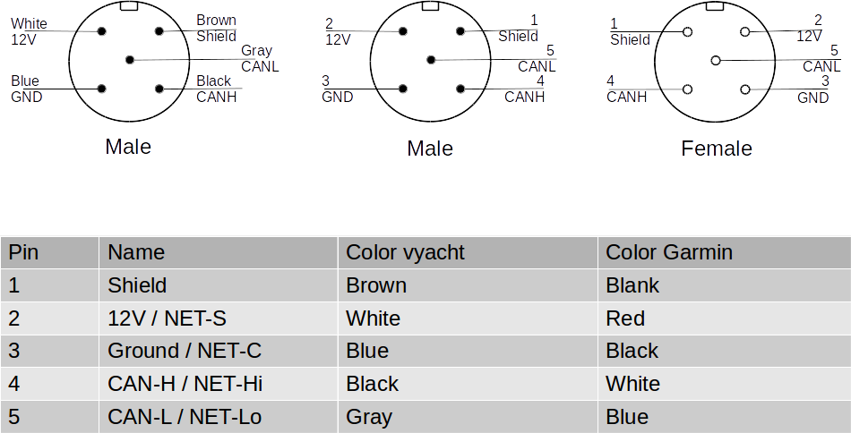
The power lines are 22awg for the light version and 16awg for the heavy version.
If you do not have a nmea 2000 network on.
Each cable uses different wire gauges for the different signal lines.
The following catalog pages contain the nmea 2000 approved network interconnect.
Obd1 engine harness diagram honda beautiful 39 beautiful honda check.
A single network cable replaces a myriad of cables used by today s methods of interconnection.
Augmenting the power helps prevent an excessive drop in voltage.
Nmea 2000 wiring diagram wiring diagram is a simplified usual pictorial representation of an electrical circuit it shows the components of the circuit as simplified shapes and the capability and signal contacts along with the devices.
Today my attention fell to this diagram in a nmea 2000 device manual from maretron.
Maretron nmea 2000 cables connectors about nmea 2000 cables and connectors the nmea 2000 standard goes beyond defining message content and includes requirements for the cabling used to interconnect electronic components referred to as the physical interface.
The nmea 2000 network accommodates navigation equipment electrical power generation and distribution systems engines and other machinery piloting and steering systems fire and other alarms and controls.
Nmea 2000 signals can be hampered by resistance which increases with cable length so keep the length for a single drop cable to less than 20 feet.
Yacht devices news update v1 07 for usb wi fi and nmea 0183 gateways.
The mini c mini change connector is used on thick backbones heavy cable.
In this episode we install the wiring necessary for our new electronics package.
If you require a longer cable run use a t junction in the middle of the run to tie in 12 volt dc power.